Cylinder head bolts
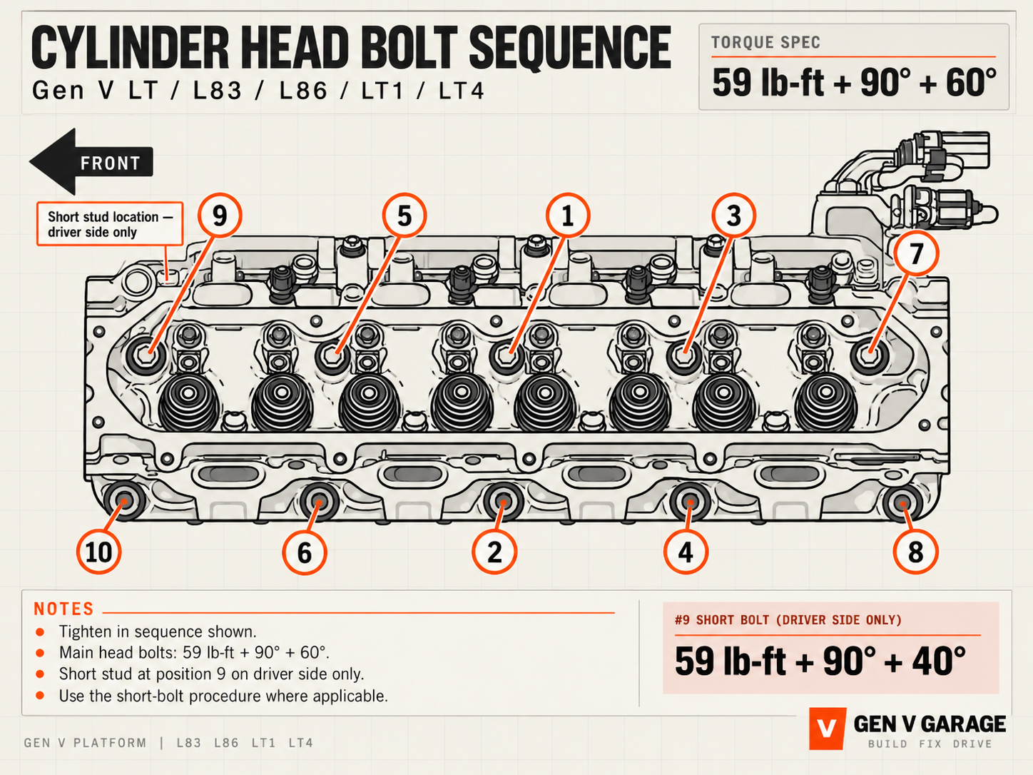
- STANDARD HEAD BOLTS
- 59 lb-ft + 90° + 60°
- DRIVER-SIDE #9 SHORT BOLT
- 59 lb-ft + 90° + 40°
PASSENGER-SIDE VIEWMirror the sequence for the opposite bank: upper row 7 · 3 · 1 · 5 · 9; lower row 8 · 4 · 2 · 6 · 10.
Intake manifold
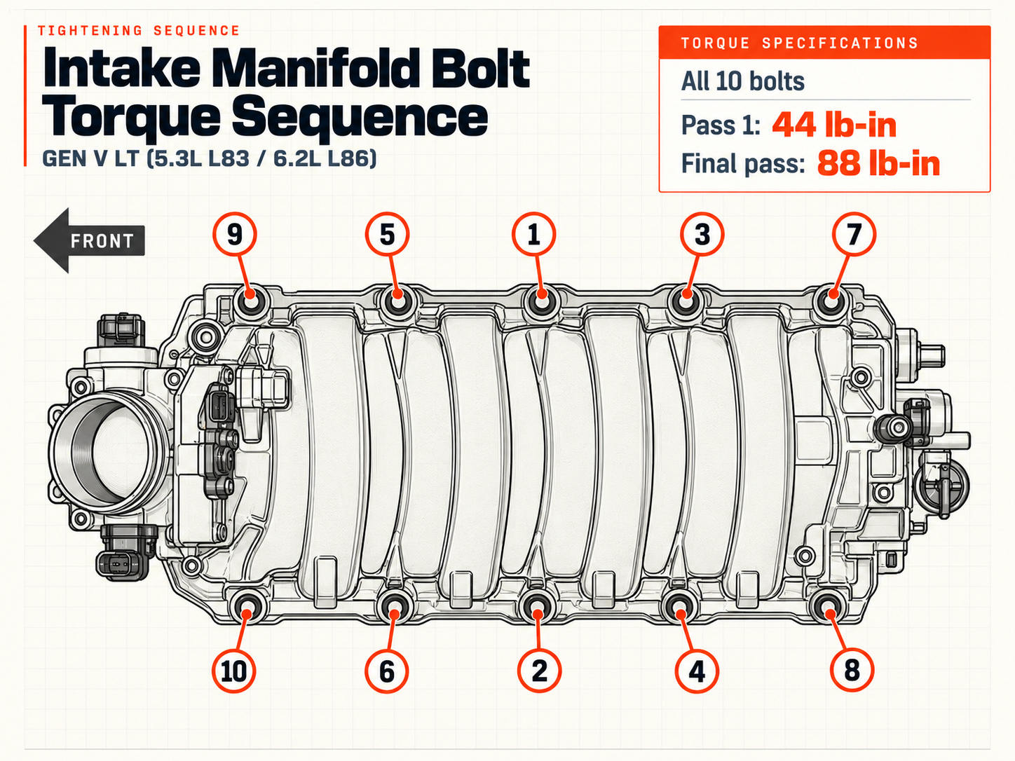
- PASS 1
- 44 lb-in
- PASS 2
- 88 lb-in
Front cover bolts
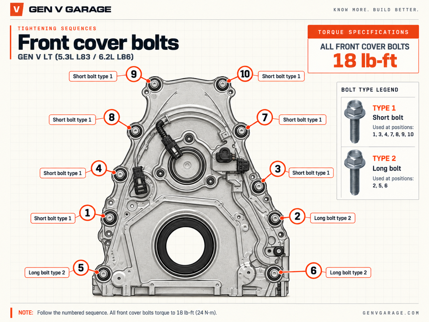
- ALL FRONT COVER BOLTS
- 18 lb-ft
- TYPE 1 · SHORT
- Positions 1, 2, 3, 4, 7, 8, 9, 10
- TYPE 2 · LONG
- Positions 5, 6
Oil pan
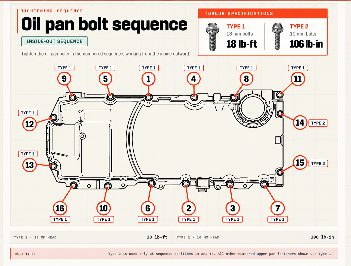
- TYPE 1 · 13 MM HEAD
- 18 lb-ft
- TYPE 2 · 10 MM HEAD
- 106 lb-in
Valley cover
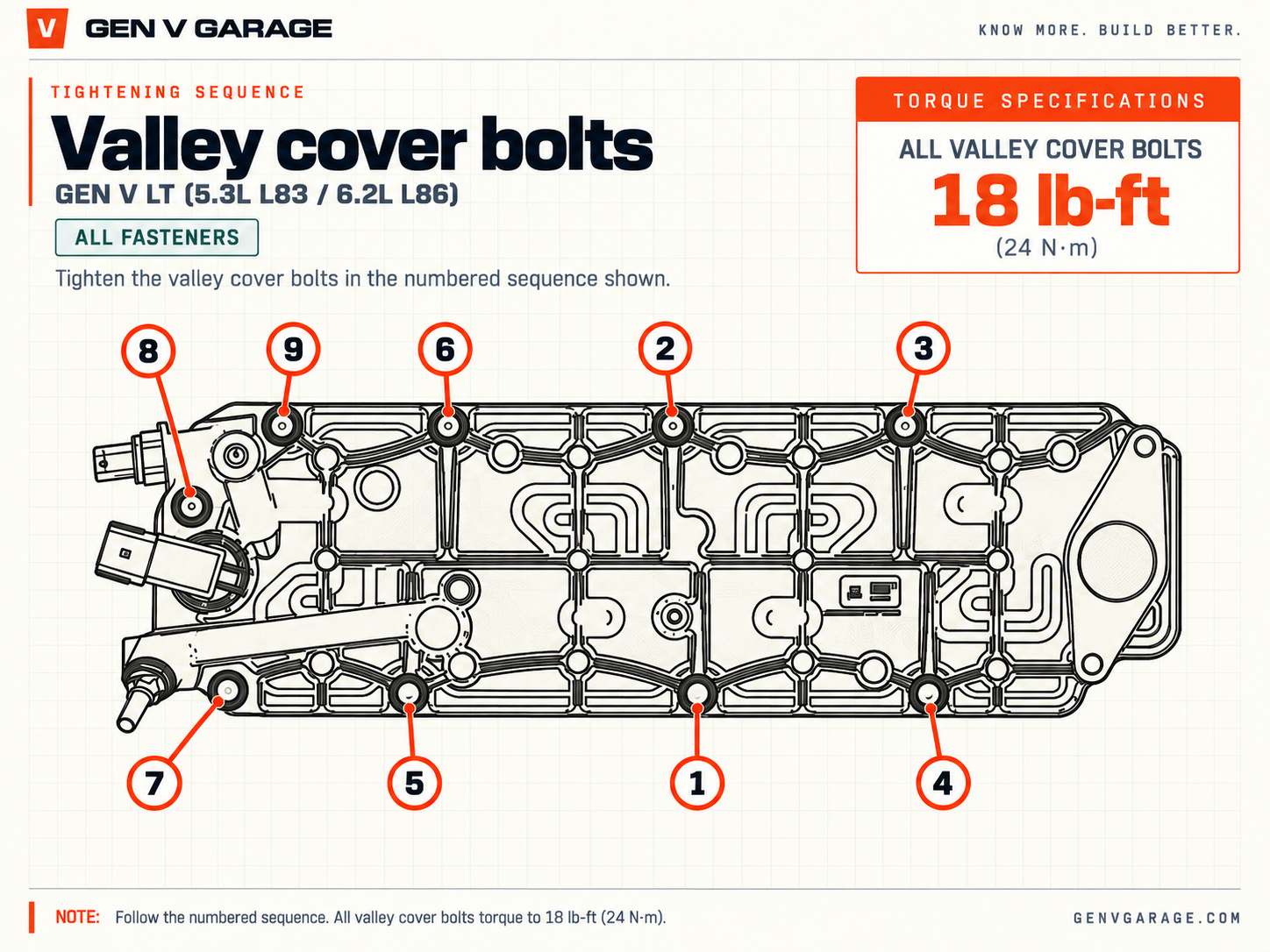
- ALL VALLEY COVER BOLTS
- 18 lb-ft
TORQUE / ANGLE TOOLS
These are the torque-angle wrenches used and recommended for this reference. Standalone angle adapters can also work; no specific budget adapter is being endorsed here.
Sequence graphics are redrawn for clarity. Torque values and special fastener notes remain in live page text so they can be verified and updated independently of the artwork.