
L83/L86/LT1/LT4 factory timing marks: phaser mark down, crank mark up.
Gen V mechanical timing is established by the relationship between the cam-phaser sprocket and crankshaft sprocket. At the timing position, the phaser timing mark is at 6 o’clock and the crank-sprocket timing mark is at 12 o’clock, with the two marks facing one another.
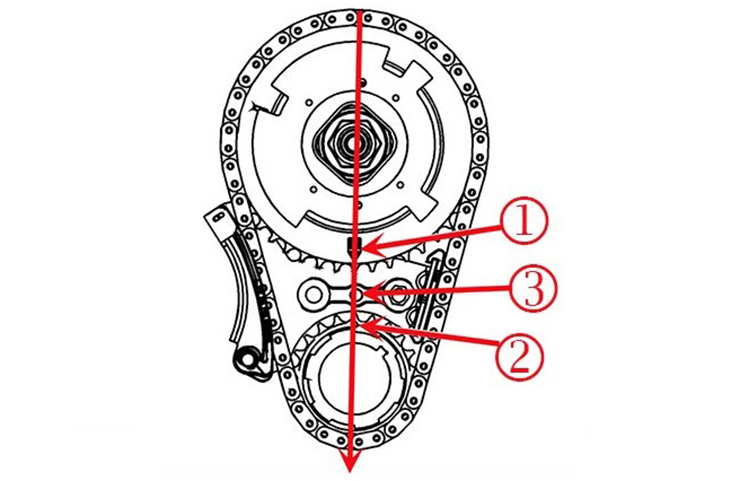
Judge timing from the actual sprocket timing marks. Do not use the nearby oil-feed hole, block casting features or an apparent visual centerline as the reference.
Why the 180° reference method helps
On an assembled Gen V engine, the crank sprocket sits behind the oil pump and the normal timing marks can be difficult to see. A practical workaround is to create a second reference on each sprocket exactly 180° opposite its factory timing mark, then use marked chain links to preserve the same cam-to-crank relationship.
They are only visible reference points on the opposite side of each sprocket. The actual factory relationship remains phaser mark at 6 o’clock and crank mark at 12 o’clock.
1 · Identify the factory timing marks
- Locate the factory timing mark on the cam-phaser sprocket.
- Locate the factory timing mark on the crankshaft sprocket.
- Confirm you are working from the actual marks before adding any temporary references.
2 · Mark the opposite teeth
On each sprocket, identify the tooth exactly 180° opposite its factory timing mark and make a clear temporary reference mark on that tooth.
GM specifies a 30-link timing chain for this alternate alignment method. Place links 1 and 30 on either side of the temporary mark on the cam-phaser sprocket, and links 15 and 16 on either side of the temporary mark on the crankshaft sprocket. This establishes the factory timing relationship even when the original sprocket marks are difficult to view.
Do not eyeball a tooth that merely looks opposite. The usefulness of this method depends on the temporary reference being directly opposite the factory mark.
3 · Establish chain reference links
Use the 30-link chain relationship above to register the chain with the two 180° sprocket references. The chain is being used as an installation reference so the same indexed relationship is maintained while the original crank mark is difficult to view.
4 · Install the timing set
- Install the crank sprocket in its correct position.
- Place links 15 and 16 on either side of the crank sprocket’s 180° reference mark.
- Place links 1 and 30 on either side of the phaser’s 180° reference mark.
- Keep the chain fully engaged while the phaser is moved into position on the camshaft.
- Verify the phaser seats squarely before final fastener tightening.
Use the new torque-to-yield phaser bolt to drag an obviously unseated phaser into position. Correct the chain / sprocket position first.
5 · Verify what the reference marks established
Before final assembly, confirm that the installation corresponds to the true mechanical timing position: phaser factory mark at 6 o’clock and crank factory mark at 12 o’clock.
The added 180° marks make an obscured timing relationship easier to establish. They do not replace the factory timing marks or define a different timing position.
6 · Seat the phaser correctly
- Identify the alignment hole in the rear face of the camshaft position actuator and the locating pin on the front of the camshaft.
- Align the actuator with the camshaft locating pin while keeping the chain fully meshed with both sprockets.
- Push the actuator completely onto the front of the camshaft using the face of the actuator sprocket.
GM specifically directs installation force to the face of the actuator sprocket. Never push on the reluctor wheel while seating the actuator.
7 · Verify chain / actuator seating
Place a straightedge across the front face of the engine block. With the camshaft position actuator completely installed, the timing chain should not protrude beyond the front face of the block. If it does, stop and correct the installation before proceeding.
8 · Verify alignment, then release the tensioner
- Reconfirm the cam-phaser mark at 6 o’clock and crank-sprocket mark at 12 o’clock, or the equivalent verified 180° chain-reference relationship.
- Confirm the actuator is fully seated and the chain and sprocket teeth are completely meshed.
- Complete the application-specific tensioner fastener procedure while the tensioner remains retained.
- Only after the timing relationship and seating checks pass, remove the tensioner retaining pin and allow the tensioner to load the chain.
Do not release the timing-chain tensioner until chain indexing, actuator seating and sprocket alignment have been confirmed.
Timing-set installation is not the same as degreeing the cam
Correct timing-set alignment establishes the intended indexed relationship between the crankshaft and camshaft. Degreeing an aftermarket camshaft is a separate measurement used to verify its actual installed position against the cam card and account for accumulated manufacturing and timing-set tolerances.
For a stock / N/A combination, an OEM chain in confirmed good condition may remain appropriate. Higher-output combinations may justify upgraded timing-drive hardware.
Before you close it up
- Factory cam-phaser timing mark corresponds to 6 o’clock.
- Factory crank-sprocket timing mark corresponds to 12 o’clock.
- Any 180° temporary references were made from the actual factory marks.
- Links 1/30 straddle the phaser’s 180° reference tooth and links 15/16 straddle the crank’s 180° reference tooth when using the alternate method.
- Chain and sprockets are fully engaged and the phaser locating hole is engaged with the camshaft locating pin.
- The phaser is fully seated without applying force to the reluctor wheel.
- A straightedge across the block face confirms the timing chain does not protrude beyond the front face of the block.
- Timing alignment and seating were verified before releasing the tensioner.
- Final phaser-bolt and timing-drive fastener procedures match the exact application.
Technical reference: GM Gen V timing guidance for the L83/L86/LT1/LT4 family and application-specific service information. Verify the exact timing-drive hardware and fastener procedure for the engine being assembled.